
SimpleDriver v2.3 in English!
Introduction
SimpleDriver v2.3 is a Tesla coil driver/controller board designed for use with DRSSTC/QCW DRSSTC topologies. It's main features are phase-shifted QCW operation, freewheeling current stabilization, and powerful output driving stage – for use with up to CM400 IGBT bricks.SD v2.3 was not designed for use with SSTCs or induction-heaters… Yet. :)

Feature list
Despie the name — SD v2.3 is targeted for advanced coilers and is packed with practically every up to date coiling technology regarding dual-resonant designs:- Phase-shifting QCW DRSSTC mode
- External buck QCW DRSSTC mode
- Classic DRSSTC mode
- Forced start mode
- Phase correction circuitry
- OCD circuitry(current protection)
- Undervoltage lockout feature
- Interrupter malfunction detection
- Powerful driving stage with 4X FDD8424H
- Passive dead-time for output stage protection
- Fiber optics input (IF-D95T)
- SimpleInterrupter-compatible
- DAC input for controlling OCD current using SI
- Variable driving stage output voltage
- Debug feedbuck generation
- Power-up delay
- Freewheeling/PulseSkip OCD mode for DRSSTC
- AltShift — heat management modes in phase-shifted operation
Connecting the power section
SD v2.3 has 4 driving outputs — «D+», «D-», «S+», «S-»:D+, D- pins output direct feedback signal (unless AltShift feature is used in phase-shifted QCW mode).
S+, S- pins output inverted feedback signal in DRSSTC mode, and phase-shifted in QCW mode (unless in ext. buck converter mode).

Here's a simplified connection to a full-bridge, with dots indicating GDT winding polarity. Note that separated primary/secondary GDT windings were shown for case study and should be twisted in real-life GDT, resistor-diodes on IGBT gates were also not shown — refer to "Application Circuit" for more details. DRSSRC and phase-shifted QCW modes share the same connection, which lets user switching between two using the «QCW» jumper.

Current and feedback transformers are connected as shown on the picture above. OCD transformer can be connected either way, it's polarity does not matter. Meanwhile, feedback transformer's polarity can be flipped using «Inv» jumper.
Should be noted that feedback/current transformers should never be placed in between MMC capacitors and primary winding – high voltage is generated in this spot during operation, it can break through transformer's insulation and damage the driver.
Connecting the interrupter
There are two ways to connect the interruption signal – by using P13 header, or by using the fiber optics input.P13 header consists of 5V, GND, and INT pins which are self-explanatory, and also the DAC input that allows user to control the OCD threshold voltage externally(check OCD section for more info). Here's how SimpleInterrupter connects to the SimpleDriver:

NOTE: Two grounds are used as a precaution, since disconnecting GND wires from interrupter while leaving 5V wire will set the interrupter's out to 1, which will most likely cause any live DRSSTC to explode.
If the IF-D95T fiber optics input is installed – note that it's output is directly connected to the same line as the INT pin, both optical and electrical inputs can't be used simultaneously. IF-D95T's output can be disconnected by removing the nearby R64 0805 jumper. In the latest version R64 is absent by default, while the IF-D95T is present.
Power supply and UVLO
It's recommended to use at least 2A 24V switching mode power supply.Mains transformers can also be used, but with larger filtering electrolytic cap and target voltage of 28V.

Input voltage can range from 24V to 30V DC. Below 22V undervoltage lockout will disable the driver after finishing up the last feedback period. Higher input voltage than 33V will result in driver malfunction.
It's possible for the driver to go into UVLO(especially while in QCW operation) from input voltage sag due to insufficient power supply wattage, this is indicated by red LED(OCD/Error) while there is no actual overcurrent detected. In this case use more powerful power supply or bigger filtering cap.
In QCW mode driver can consume up to 100 watts in 10 ms bursts while driving the power section!
UVLO is very helpful in case the coil gets disconnected from mains supply while still in operation – driver's voltage falls down, and if it tries switching the power section with 11V signal or less – it could lead to IGBT malfunction due to instant overheat. Luckily – UVLO saves the day by disabling the driver if there are any issues with it's input voltage.

Above is UVLO circuit used in SD. Input voltage goes through resistor divider R46/R49 and is compared to on-board 3.3V rail. If input is higher than 22V – comparator stops pulling C36 to the ground and it gets charged through R44, after which there's a logic 1 on PowerGood CPLD input. This gives us both the power-up delay and undervoltage protection functionality. If other UVLO threshold is desirable – user can change the R46 resistor. It's value can be calculated in Calculatoria.
While there is no PowerGood signal – green LED is turned off.
Control jumpers
SimpleDriver's operation mode can be configured using 6 on-board jumpers.Every one of them can be set to either 0 or 1. About them in short:
1. QCW jumper, when set to 0 — sets SD to DRSSTC mode, when set to 1 — QCW DRSSTC mode.
2. Invert jumper, inverts feedback signal if set to 1. When set to 0 FB signal is direct.
3. Buck jumper in QCW mode activates Buck output(P3 header) (0 — buck is disabled), and in DRSSTC mode turns on/off the forced start impulses (0 — forced starts is activated!).
4. Generate jumper switches feedback signal to the one generated by RC oscillator (0 — feedback is used, 1 — generated squarewave)
5. PSkip jumper, in DRSSTC mode turns on the freewheeling OCD mode. In QCW — it sets the type of AltShift mode(alteration between shifted half-bridges, 0 — every interrupt, 1 — every feedback period).
6. AltShift jumper, turns on phase-shifted half-bridges alteration (1 — AltSHift is turned on, 0 — turned off)
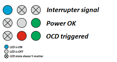
Indication
There are 3 LEDs in SimpleDriver, each having it's own color:1. Red, indicates an error. Both red and green lighting up means the OCD had been triggered.
Because OCD signal is extremely short – CPLD extends it to 10 ms.
2. Green, indicates that the power is good(above UVLO threshold)
3. Blue, repeats the interrupter signal(extended in QCW mode for better visibility).
Setting up for DRSSTC operation!
SimpleDriver is perfect for DRSSTC mode. By using it you can build powerful, up to human-sized Tesla coils, including the musical ones. Every classical feature for this mode is supported: OCD/Freewheeling, ZCS synchronization, phase-correction(prediction), forced start impulses, an UVLO. Going through this list is also required before continuing to phase-shifted mode setting.WARNING: All settings should be performed with unpowered power section!.
DRSSTC TODO list:
Step 1: Set up the basic connection as shown in «Connecting the power section».
Step 2: Set all the jumpers to 0.
Step 3: Calculate the frequency your coil will work on. This can be done in Calculatoria. This should be either higher or lower pole frequency(will run on higher pole if primary tank has higher frequency than secondary coil's resonance).
Step 4: Tune up the on-board RC-oscillator. To do this, probe P15 pad while turning the Oscillator potentiometer. Frequency should be equal to the one your coil will run at, it should be as close as ± 10 kHz.
RC oscillator is used for 3 purposes:
1. It's used for generating forced start impulses (SimpleDriver outputs first 4 periods with oscillator's frequency, and only then switches to the feedback signal). With forced start it's easier for the coil to run, especially on a desired pole.
if you wanna turn off the forced start feature and use classic start – set Buck jumper(while in DRSSTC mode) to 1.
2. Oscillator is used as timer for turning off the coil if the event as zero current crossing wasn't detected.
3. If jumper Generate is set to 1 – oscillator signal replaces feedback signal, which can be helpful for debug purposes(open loop operation).
Step 5: Set the OCD current.
This can be done either by turning R15 «OCD» potentiometer, which works as a voltage divider with output hooked to the OCD comparator… Or by providing the reference voltage externally. If you own a SimpleInterrupter(v1.2 and above) that has DAC output – you can hook it up to SD and set the OCD value using SimpleTesla app settings menu with inbuilt calculator. However, if on-board potentiometer is preferred – calculate it's output voltage using Calculatoria.
Important: switching between DAC input(external OCD) and OCD potentiometer is achieved by installing R65 and R66 0R jumpers. Originally, SD is set to work with on-board potentiometer.
Step 6: Switch «Generate» jumper to 1, connect the interrupter to «INT» pin on P13 header and start sending impulses(blue LED should light up). Now check the signals on IGBT gates without turning on the power section, if the results are satisfactory(IGBTs in full-bridge should switch in chessboard pattern) – switch «Generate» jumper back to 0.
Step 7: Apply voltage to the power section and turn on the interrupter. Since it's still a debug stage – voltage should be mains-isolated with a transformer and lowered to 50-80V. Variac + isolation transformer are great tools for going through this step.
Step 8: Set the polarity of your feedback signal. For this, connect your oscilloscope to the current transformer and observe closely. Tesla should «start up» on every interrupter impulse, that peculiar sinewave with rising amplitude should be present. Otherwise, use «Invert» jumper for flipping the signal from feedback transformer.
Step 9: Set up the phase corrector(a.k.a. the predictor). This is one of the tricky parts, and you'll also need a 2-channel oscilloscope. So, connect 1'st channel to the power section's output(middle point of one of the half-bridges), and 2'nd channel to the loaded current transformer. Then, turn the R13 «Phase» potentiometer until 0 of current sine matches the edge of squarewave one of half-bridges outputs. If you're past setting up the predictor – congrats, it'll be much easier from now on. :)
Step 10: This one is necessary if you're going to use SimpleDriver in a QCW mode. Tune up the amplitude of sawtooth oscillator, which is used in phase-shifting analog-digital logic. For this, apply external ramp signal to the interrupter input, and turn the «Saw current» potentiometer while observing the signal on «Saw current» pad. The signal should look like a sawtooth and go from 0 to 5V.
This procedure should still be done while SD is in DRSSTC mode(«QCW» jumper is set to 0), but does not require the power section connected.
Step 11: Hooray, we're ready!
Setting up the phase-shifting mode!
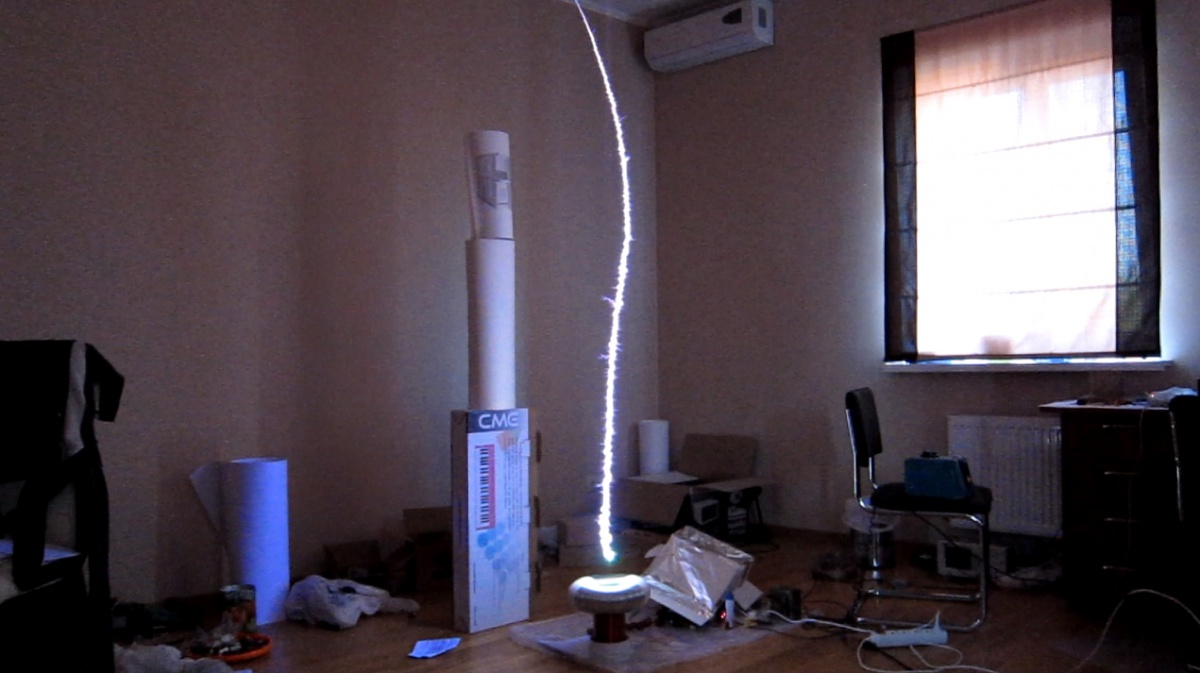
QCW mode allows generating streamers of phenomenal length, sometimes up to 1:10 in ratio compared to secondary coil length. This is achieved by gradually growing the streamer, which results in minimal branching – this way all the energy goes into growing one large streamer instead of many smaller ones, like in case of classical coils without power control mechanism(interrupted SSTC/DRSSTC). By using phase-shifting there's also no need for bulky and complex external buck-converter, power control is achieved solely in a way power section is being driven by the SimpleDriver.To learn how phase-shifting works with a full bridge – please refer to appendix A.
To see how phase-shifted QCW was implemented in SD v2.3 – see appendix B.
At the beginning of a QCW cycle there's usually a problem with coil not having sufficient power for the current transformer to pick up the feedback and start self-oscillation. In SimpleDriver it's solved by forcing the start with 8 generated pulses at the beginning of every interrupter cycle. After that SD switches back to the feedback signal.
QCW TODO list:
Step 1: Set up the driver for DRSSTC operation(as shown previously).
Step 2: Switch SimpleDriver to QCW mode. For this – switch «QCW» jumper to «1».
Step 3: Connect your ramp signal generator to SimpleDriver's interrupter input, «INT» pin on P13 header(blue LED should light up). Check whether SimpleDriver starts up for every ramp cycle, for this probe the «start» pad with a scope. Normally the signal is 1, 0 indicates that the SD had started up for a QCW cycle.
Step 4: Apply voltage to power section from isolated variac(50-80V is enough) and check how your Tesla works. If it starts up – proceed to testing with mains voltage.
Step 5: Ready!
P.S. «Ramp» is an analog signal that's used instead of classic interruption to control the power output of a half-bridge. In classic QCW DRSSTCs it's usually in a form of «sawtooth» with a pause between periods(1-10 ms tooth going from 0-5V, every 1-10 Hz).
Phase correction
To achieve true zero-current switching and high efficiency – feedback signal should be phase shifted to compensate delays in the control and driving sections. This is important in high-power applications where charging up large transistor gates can cause up to 400 ns delay in the system, resulting in hard switching which eventually causes unwanted effects like streamer length loss, powerful inductive spiking on the collectors/drains of power transistors, excessive heating, and eventually malfunction of the power section. This is especially important in QCW mode where power section is required to work for prolonged periods of time(up to 10 ms, compared to DRSSTC's 120 us).To solve the phase shift problem – two-stage phase-conversion is utilized in SimpleDriver. First stage statically compensates the phase for more than it's actually needed, and second one allows user to add a precise correction. With this topology no exotic components are needed, such as nowadays scarce powerful variable inductors.
First stage consists of a static LR circuit and fast comparator. LR(L1, R10) at the same time serves as burden load for current transformer and shifts the phase, while comparator filters the signal of unwanted noise and translates it into 5V logic signal.
R3 and С1 implements time hysteresis. In very powerful applications it may be needed to replace С1 with 1nF for CM300, and 2.2nF for CM600.

Second stage consists of an RC circuit of R13 и C23. It provides variable delay to compensate the excessive phase shift of a first stage. C23 can be replaced with a higher capacitance value to get wider second stage compensation range.
In case first stage does not provide sufficient static phase shifting – L1 can be replaced with a bigger value, or R10 with a smaller one. You can calculate the values in Calculatoria.
Overcurrent protection
The driver includes standard OCD unit for overcurrent detection. When triggered — SD indicates it with the red LED and ignores the rest of interrupt impulse after finishing up the last feedback period – this turns the coil off softly, when there's 0 current going across power transistors. OCD threshold can be set in 2 ways:- Classical — using an on-board potentiometer. R65(«Pot») should be installed, and it is by default. For setting the OCD value, turn the potentiometer while observing voltage on «OCD» pad. For calculating your current transformer parameters — you can always use Calculatoria.
- With SimpleInterrupter, by setting OCD value from the settings menu. For this R66(«Pot») should be removed, and R65(«DAC») present on board SD, which disconnects the potentiometer from OCD comparator and instead connects the «DAC» pin from P13 header. «DAC» pins on SI and SD should be interconnected with a wire. DAC stands for «digital-to-analog converter», and it's a digital periphery on board STM32F100C8 – SI calculates and outputs analog voltage for OCD comparator, thus letting the user setting it digitally(in amps) from SimpleTesla control app.

It's worth mentioning that the OCD value should always be set to slightly above the in-air operation current, so the OCD wouldn't trigger when the coil strikes air, and would when it strikes the ground. Setting the current way above this value won't add to the streamer length, but instead will make the coil heat more and be less reliable while it strikes the ground.
Current stabilization
Also known as «Pulse Skipping» or «Freewheeling» – this is more advanced current protection mode, where DRSSTC not just shuts down when the OCD threshold is reached, but instead continues operation while stabilizing the current in primary tank circuit at the safe level. It's possible by skipping separate feedback periods while the primary tank circuit continues the oscillation because of high Q-factor. This allows running the DRSSTC with much larger interrupt impulses(typical vale is 1-4 ms), thus getting much larger and interesting looking streamers. Also – more spectacular ground discharges.Current stabilization can be activated by setting the «PSkip» jumper to 1. Operation in this mode requires precise OCD threshold setting and good attention to power section's cooling system.
Primary tank current in this mode:

Signal on power transistor gates:

Alternating half-bridges in phase-shifted QCW mode
In classical phase-shifted QCW, one half of the full bridge works in ZVS/ZCS mode(direct half-bridge), and the second one – only in ZVS(shifted half-bridge). Because of this – one half of the full bridge heats up lot more than the other one, resulting in faster overheating – the QCW DRSSTC should be turned off with only one half-bridge reaching critical temperature, thus reducing the operational time. By balancing the heat dissipation — it's possible to greatly prolong either the operation time or BPS rate from QCW DRSSTC coil. We never seen this technology implemented in any other driver, so we had the dare to give it a name — AltShift. :)In SimpleDriver there are two modes of phase-shifted full-bridge heat balancing:
1. Mode in which shifted half-bridge change places every interrupt cycle, i.e. after every zap.
To activate it, set jumpers to (AltShift = 1, and PSkip = 0). This is a very simple mode and it does not require any changes to the classic QCW DRSSTC circuit. We recommend using it in phase-shifted mode.
2. Mode in which shifted half-bridge change places every feedback cycle.
This is a very advanced mode that provides even better heat dissipation balancing, and without the necessity for interrupt to occur. It requires good attention to gate drive quality(isolated drivers are recommended, but was successfully tested with GDTs too). For activating it, set jumpers to (AltShift = 1, PSkip = 1).
In theory, this mode will allow users to control QCW with external audio signal, although operation in such a mode wasn't tested yet.
Schematic for SimpleDriver v2.3
It can be obtained from here.Application circuit
Here's an example of a typical DRSSTC/phase-shifted QCW DRSSTC built with SimpleDriver: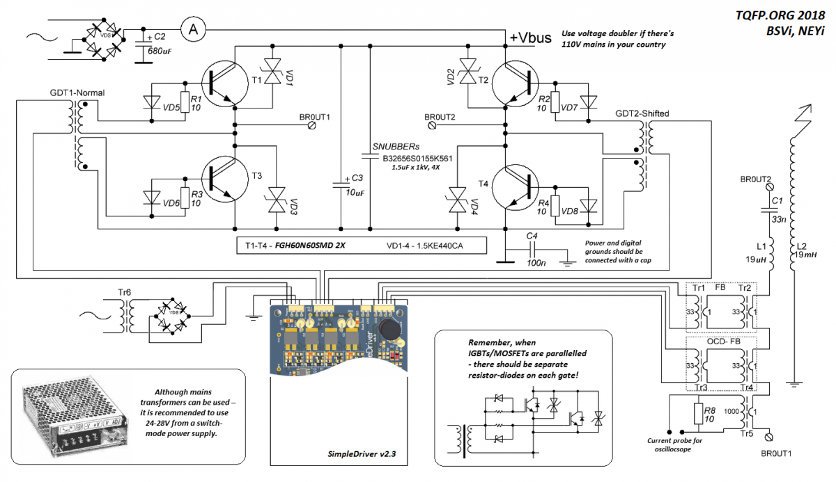
Shielding case
SimpleDriver should always be run from a shielded case if it controls a live Tesla coil to prevent interference.Fortunately, from now on v2.3 comes inside a custom aluminum case specifically designed for it.

Note that the case should have electrical connection with the driver's ground, for which there are two GND inputs present on the power header.
Appendix А: Theory of phase-shifting operation
Phase shifting — a method for controlling power output from a full-bridge(0 to 100%) without any additional hardware needed, simply by the way full-bridge is being controlled. It works by shifting in time control signal for one of the half-bridges(2 of which make up 1 full-bridge). On the output from a bridge we get a PWM signal(dead-time, to be precise), duty cycle of which equals to the amount of shift between shifted and direct-driven half-bridges(180° shift = 0% duty cycle, and 0° shift allows 100% power to come through). Phase-shifting is more advanced than direct PWM drive and has two direct pros:1. With direct PWM both half-bridges would experience hard-switching, or in other words – they'll switch when there's current running through transistors, which leads to excessive heat dissipation. With phase-shifting half of the full-bridge is shifted softly.
2. Phase-shifting is compatible with GDTs, since control signal for shifted half-bridge preserves 50% duty cycle, it's only shifted in phase compared to directly-driven half-bridge.
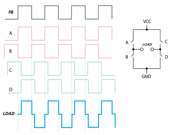
Note, how A/B half-bridge(driven with red signal, that's in sync with FB) is always being switched when there's no current running through the load – this means it's being switched in ZCS(zero-current switching), and there's minimum heat being dissipaded during it's operation.
However, C/D half-bridge(driven with green signal, shifted compared to feedback) – it's being switched always when there's current running through it.
That's the only con of phase-shifted technology, half of the full-bridge is going through hard-switching and this requires additional attention to gate-drive quality and heat management. However, we believe that AltShift features of SD will help distributing heat-dissipation across the power section.
If you're curious to see a shifted full-bridge simulation – it can be found here.
Appendix B: Phase shifting implementation in SimpleDriver
The basis for phase-shifting action in SD is comparing two sawtooth signals.Let's see in deep details how this process works:
Ramp signal in PWM form, either from "INT" pin on P13 header, or from IF-D95T optics reciever is applied to point "A". There it's being double-stage low-pass filtered with R37-C27 and R38-C28, which convert PWM ramp into an analog ramp that could be used with comparators from point "B".
NOTE: SD can work with analog ramp applied to point "A", but this approach has certain restraints – you can't send analog signal over optics, since IF-D95T is a digital device, and SD also can't be used with external buck this way – since it relies on externally generated PWM ramp for sending it to P3 buck output header. With analog ramp SD can work only in phase-shifting mode.

Let's continue: from point "B" analog ramp is being applied to inputs of LM393 and MCP6561 comparators. LM393 is used for generating start signal, analog signal is being compared to voltage devider's output of 0.1V, generated by R40-R43. For suppressing residual PWM noise – hysteresis with R41-C29 was added.
Eventually, on point "C" we get digital signal that indicates presence of an analog signal on point "B", an it is used by CPLD for starting the QCW cycle. In other words – it's an interrupt signal rectified from a presence of ramp signal(0 = Start, 1 = Ramp Not Present).

Now the interesting part – how the phase shifting analog-digital logic works.
There's a current source circuit formed with transistor Q4 and resistors R34, R32, R19(potentiometer). It charges the C25 capacitor, that's being discharged by Q6 every front of a feedback signal, thus creating a sawtooth with frequency equal to the one your coils runs at on point "E".
This approach hovewer needs manual R19(«Saw current») tuning so the C25 cap would have enough time for being charged to 5V before new feedback edge will discharge it. SD has special protection logic for dealing with situation when ramp has higher voltage than sawtooth signal.
Eventually, the fast comparatior MCP6561 compares analog ramp "B" signal with sawtooth at point "E", forming a crude ADC converter. Signal on point "F" will be a pulse, length of which will vary from 0 to 0.5 of the feedback period. 0 if analog ramp voltage is 0, and 0.5 of a period if it's equal to 5V.

This voltage-measuring pulse at point "F" is special, because since it's equal to half-period of a feedback frequency – now we can subtract it from a rising edge of a feedback signal, and add it back to the falling edge… Resulting in, voila – phase shift!
That's also equal to the measured analog signal on point "B", 0V = 0° shift, and 5V = 180° shift, which now allows us to control the coil's power output from 0 to 100%. I agree, the explanation can look bit complex, but that's how this analog-digital witchery really works. :)
Same functionality could be implemented digitally, but would require quite a large FPGA working at frequencies of hundreds of MHz(up to 400 MHz for digital phase compensation), and for processing external analog signal it'll also need an external fast ADC(up to 1 MSample/s). In the end, we though that implementing most of the functionality with analog-digital approach would be a much more elegant solution. That's also where the name comes from – SD provided complex functionality with simple hardware.
Implemented designs
The article wouldn't be complete without some real-life designs demonstration.Here are some photos of of QCW DRSSTCs based on SimpleDriver:
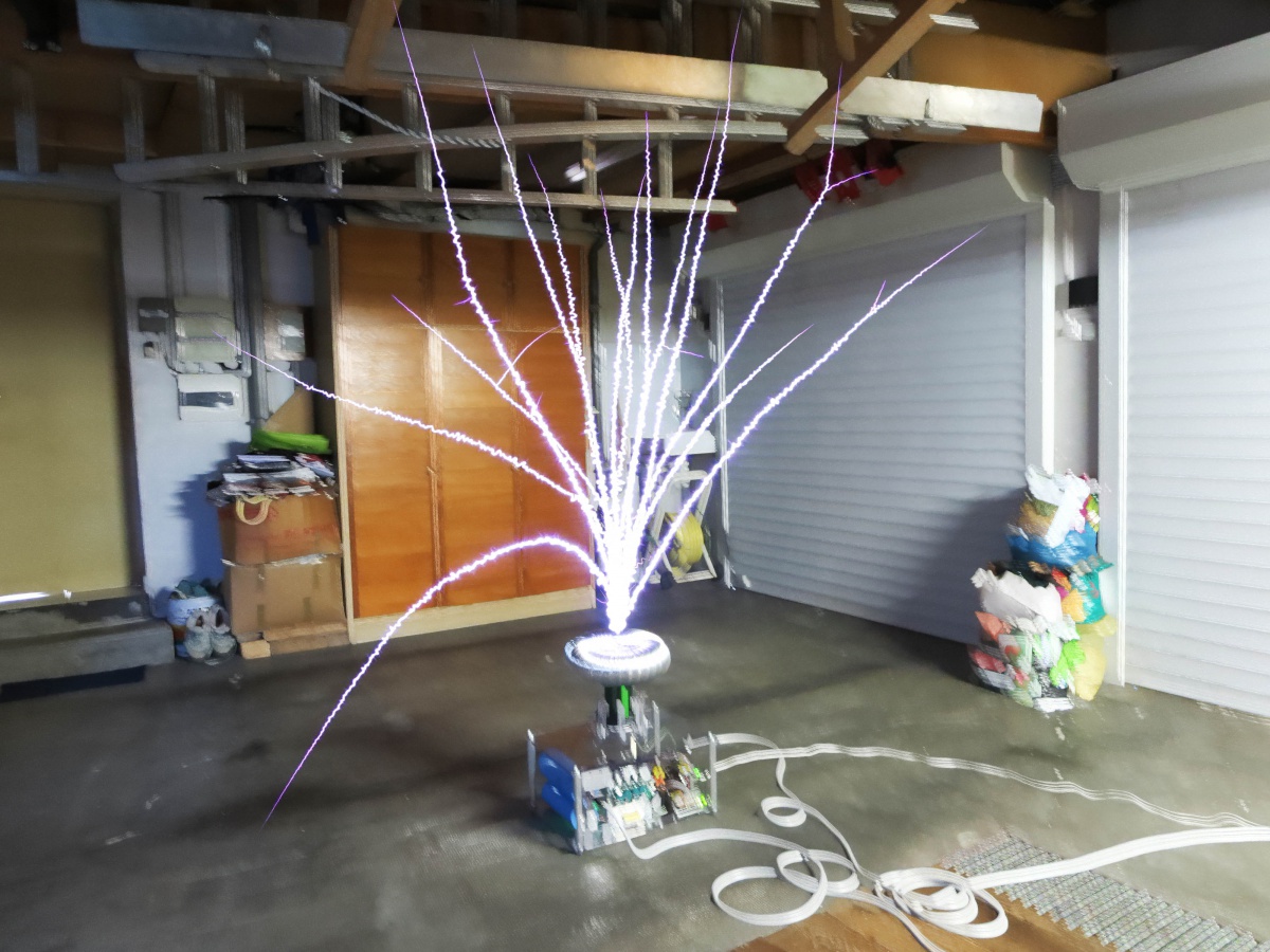
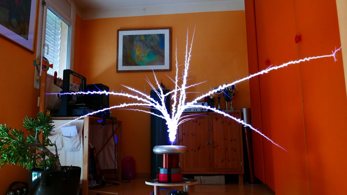
P.S. Warmest thanks to Florian, Stanislas, ArcSound, Pigball, and Tesla Technologies for providing feedback/results regarding SD. :)
Contacts
If you're curious to purchase an SD v2.3 – I can sell you one for $95 if it's just a board, or for $120 if it's in aluminum shielding case.Feel free to write me an E-mail on the matter, or if you simply got questions regarding driver/coiling in general – I don't mind chit-chats. :)
eugene.negrobov@gmail.com
Stay creative and curious,
-Eugene
0 комментариев